NDT Concrete

IDS C-thrue GPR Concrete Scanner

NDT Concrete owns and employs IDS C-thrue, the state-of-the-art concrete scanning GPR system. Besides, we are proud to be the official distributor of IDS GPR products in the state of Florida. In the following, we will explain the main features of C-thrue so that you can see why it is the best concrete scanner currently available. 

concrete scanning orlando tampa daytona jacksonville miami florida
Fig. 1. C-thrue in action

1. How is C-thrue designed?

The main focus of IDS when designing the C-thrue was that it would be a compact and portable concrete scanning system. Equally important, it should provide as much data as possible with minimal effort spent on data collection. As you can see, the all-in-one system depicted in Fig. 2 perfectly meets those design requirements. First, it incorprates into one small unit all necessary GPR components. Second, with two antennas, for the same scanning effort, it provides twice as much information as compared with the conventional GPR. 

IDS C-thrue GPR
Fig. 2. IDS C-thrue all-in-one compact GPR system
C-thrue Specifications
IDS C-thrue GPR Specifications

2. What is its biggest advantage?

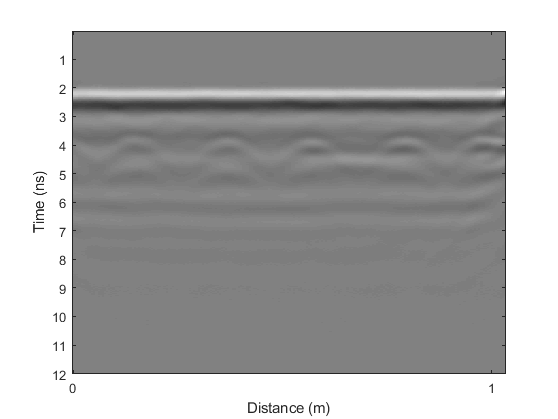
As you may already know, antenna polarization is a very important characteristic of a GPR system. That is to say the orientation of the antenna will have a big effect on what you can see in GPR images. To illustrate this concept, Fig. 3 and Fig. 4 show B-scan images obtained from the same survey line using different antenna orientations. As can be seen, top rebars in Fig. 3 appear much more clearly than those in Fig. 4. However, in Fig. 4, we can observe better the rebars at slab bottom. The reason is when a metal bar lie in the same direction as that of the antenna dipole, they will produce much stronger reflection, however will create a shadow area below it. 

That being said, you may want to know a detail that IDS alrealdy place the two antennas of C-thrue unit in two perpendicular directions. As a result, for each scan line, you automatically have what is known in GPR theory as dual or double polarization data. As a clarification, you may be able to obtain the same data set with the conventional GPR system. However, that can only be possible with the following two conditions. First, the system must allow you to adjust the antenna orientation. Second, you have to scan twice for each survey line.

GPR Polarization 1
Fig. 3. Primary orientation (antenna dipole perpendicular to scanning direction)
GPR Polarization 2
Fig. 4. Secondary orientation (antenna dipole parallel to scanning direction)

3. Example results from C-thrue data

3.1. Three-dimensional (3D) concrete imaging

With regard to data interpretation, you can buy from IDS either C-thrue or GRED HD 3D advanced data processing software. However, you can also use your own program if you are able to do so. That said, in the video below we present a typical 3D image generated by our program from C-thrue data.

3.2. Two-dimensional (2D) concrete imaging

As you can see, from a 3D image like the one above, we can extract various types of information. For example, we can identify concrete cover thickess for each individual rebar. Similarly, we can generate a plan view (2D  image) of a slab that shows rebar locations as illustrated in Fig. 5. Obviously, those information are valuable if are planning for renovation of an existing slab or for quality assurance of a new one.

2D Concrete Imaging Orlando Tampa Daytona Jacksonville Miami Florida
Fig. 5. Plan view of rebar arrangement in a 6.5m x 2.5m slab