NDT Concrete

Ultrasonic Concrete Imaging

Beside GPR, we also provide structure scan with MIRA –  an ultrasonic concrete imaging equipment. In the following, we will explain briefly how the MIRA works and what are the benefits, limitations of using it compared with GPR.

1. Background

MIRA is a concrete imaging device developed in the early 2000s by Acoustic Control Systems. It utilizes an array of transducers to transmit and receive ultrasonic shear wave signals. Specifically, in its latest generation depicted in Fig. 1 & 2, the MIRA consists of 48 transducers. Those are grouped into 12 blocks with the longitudinal spacing of 30 mm. In one block, the distance between adjacent transducers is 25 mm. With respect to time resolution, the MIRA can operate with a center frequency any where between 25 and 85 kHz. During its operation, the laser light assists the operator in positioning the MIRA correctly on marked survey locations.

Ultrasonic Concrete Imaging
Fig. 1. MIRA device in operation
Fig. 2. MIRA's DPC transducer

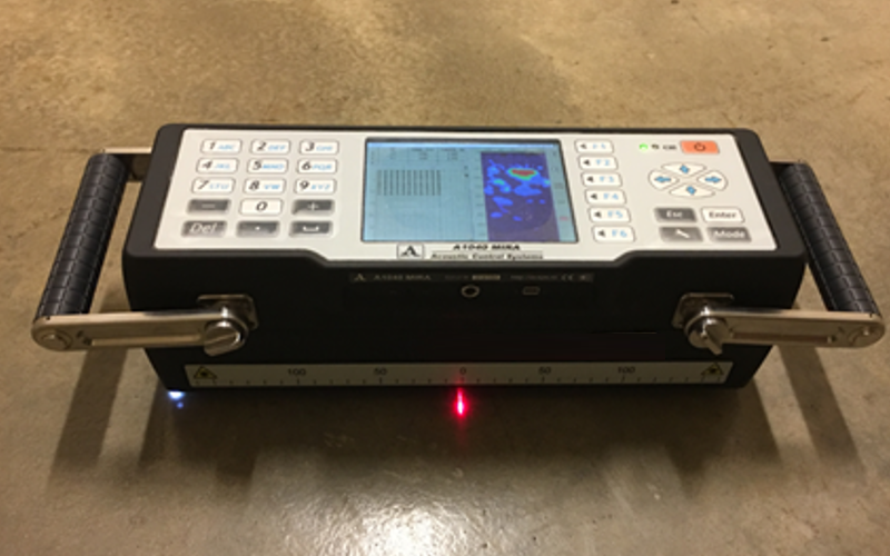
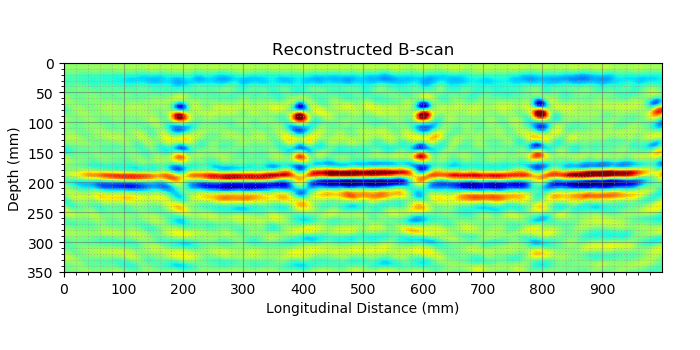
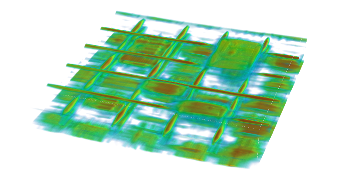
With regard to operation, the MIRA can work in either one of three modes, namely calibration mode, B-scan mode and map mode. First, the calibration mode is to change the settings of the device and data collection parameters. Second, the B-scan mode is to check the equipment performance or to quickly scan a random spot on the surface. Finally, the map mode is to scan an entire area of the test structure. Only in this mode, the MIRA will be able to generate a 3D visulization of the structure.

2. MIRA Application

The only application of MIRA is to image the interior of concrete. Similar to GPR, it also uses SAFT algorithm to rebuild images from individual A-scans collected by its transducers. Specifically, since MIRA has 12 blocks of transducers, it creates a total of 66 waveforms for each scan location. Therefore, suppose we have 10 MIRA scans for a survey line, we will have a total of 660 A-scans those can be used as the inputs for the SAFT algorithm. The output of this step is a cross-sectional image of concrete as presented in Fig. 3. Once we have a number of such images, we can generate a 3D view of the survey object via interpolation. An example of it is provided in Fig. 4.

Fig. 3. MIRA B-scan
Fig. 4. MIRA 3D visualization

3. MIRA versus GPR

As you have seen, GPR and MIRA utilize the same algorithm  to image concrete. However, the difference between them is that, while GPR transmits and receives electromagnetic waves, the MIRA sends and receives ultrasonic signals. Because of the nature of each wave type, each device has its own advantages and limitations, which are listed below.

  • GPR scans a structure much faster than the MIRA does. This is similar to a comparison between the velocity of light and velocity of sound.
  • MIRA can image thick concrete structure while GPR cannot. The reason is EM wave attenuates quicly in concrete due to dielectric loss.
  • GPR can detect corroded rebars while the MIRA is insensitive to the corrosive environment.
  • MIRA can detect hair-like concrete delaminations while GPR can only see big ones.
  • MIRA can identify steel bar debonding while GPR cannot.